1.4. Scanning unit
1.4.1. Description of components
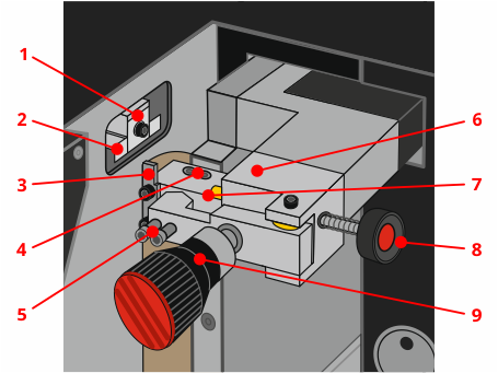
- Measuring probe
- Measuring probe plate (plate)
- Reference element
- Adjusting screws for elements supporting the correct positioning of the original key in the fixed part of the clamp
- Adjusting screws to help position the original key correctly in the moving part of the clamp
- Clamp holding the original key
- Element indicating the scanning range of the key profile
- Button for selecting the key profile scanning range
- Clamp knob
Warning
The measuring probe plate is a precise and delicate component. Take special care not to damage it, e.g. by bending it.
1.4.2. Principle of operation of the scanning unit
The scanning unit works by closing an electrical circuit between the probe and the workpiece. When contact is made, the axis movement is stopped and the current value determining the position is read. A detailed measurement of the workpiece is performed by a measuring plate which, when in contact with the workpiece, allows its coordinates to be determined accurately.
The measuring probe has a protective function for the measuring plate in the form of additional limit switches. If pressure is applied to the probe and the electrical circuit is not closed, the probe deflects and one of the safety switches is activated. This causes the movement of the axis in question to stop and triggers the appropriate action depending on the procedure currently being performed.
Warning
Usually, the protective function of the measuring plate is activated when an attempt is made to scan a dirty key. Such situations should be avoided due to the risk of damage to the measuring plate and distortion of the scanning results.
Danger
The movement of the axes is continuously monitored for contact between the probe and any components. If contact is detected where it should not occur, the machine will stop immediately and an error code will be displayed. For this reason and for safety reasons, it is not permitted to leave any objects within the scanning unit.
1.4.3. Preparing the original key for profile scanning
To ensure that the key profile scanning process runs smoothly, the following conditions must be met:
- Type of material: The key must be made of conductive material (e.g. metal) because scanning is performed by closing an electrical circuit with a probe and the key being scanned.
- Surface cleanliness: The surface of the key to be scanned must be thoroughly cleaned. To do this, use the brushes included in the kit or a soft brush and mineral spirits.
- Avoid aggressive cleaning methods: The use of rotating brushes (e.g., metal wire brushes) is not recommended, as they can permanently damage the original key and scratch the scanned surface.
- Removal of additional elements: The key should not contain any additional items such as wheels or key rings, as these may interfere with the scanning unit.
1.4.4. Fixing the original key in the scanning unit
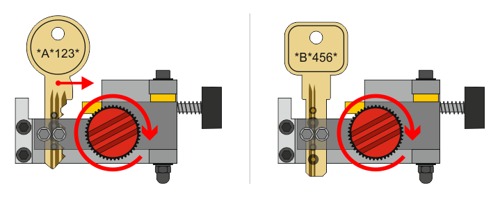
For single-sided keys, the upper stop (the so-called base) must be on the right-hand side, i.e. next to the element indicating the profile scanning range (according to the information sticker on the housing).
The key must be fixed in the correct position by pressing it with the movable part of the clamp and tightening the knob with sufficient force to hold the original key securely during scanning, but not so much that it could damage the original key or machine components.
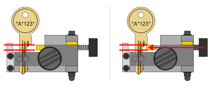
The area on which the key profile will be scanned is determined by the height of the measuring probe's contact point with the surface of the original key and is 4 mm. The position where the key will be scanned can be determined by extending the element indicating the profile scanning range by pressing the button on the right side of the clamp.
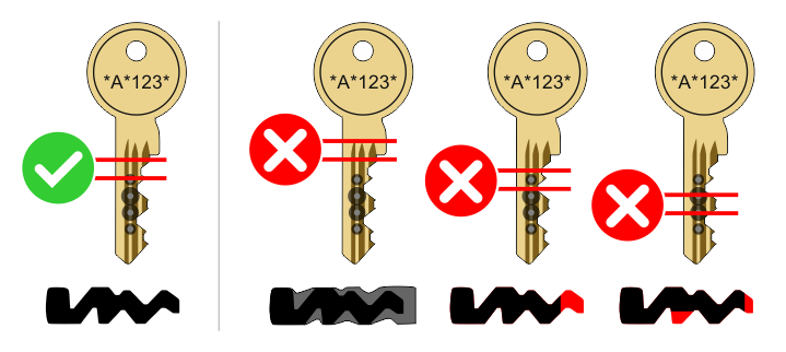
The fragment of the key from which the profile will be scanned should contain its full, undistorted cross-section, without any cuts or drill holes. In the case of single-sided cut keys, this fragment can be determined using a caliper and measuring the key from the back (the so-called base) to the highest point on the side of the cuts.
This is usually located just below the upper stop (the so-called base), which is important for making an accurate copy of the key, as this part of the profile is usually the least worn.
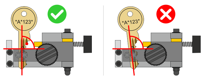
The cuts (grooves) of the scanned key profile must be perpendicular to the scanning unit clamp; usually, the correct position is determined by pressing the key into the profile groove with the movable part of the scanning unit clamp. If this is not the case, select another profile groove or correct the position manually.
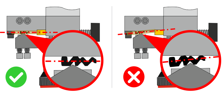
The key head (i.e. the axis of its profile cross-section) must be positioned parallel to the fixed (stationary) plane of the scanning unit clamp. To do this, select the correct groove of the scanned key profile, which will hold the key in the correct position when the clamp knob is tightened.
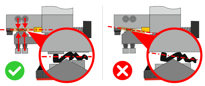
For non-standard keys that cannot be positioned correctly in the scanning unit, use the adjustment screws in the clamp to lock the key in the correct position using additional support points.
Use a 3 mm Allen key from the tool kit provided to adjust these screws. Additional elements fixing the position of the key in the fixed (immovable) part of the clamp are removed by tightening the screws in its upper part. The screws in the movable part of the clamp form additional support points with their ends, so they should be tightened gently so as not to damage the original key profile.
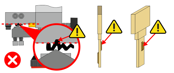
Protruding elements of the key profile must not protrude beyond the contact surface of the key with the fixed (stationary) part of the scanning unit clamp.
Warning
Failure to comply with this recommendation may result in damage to the measuring probe plate and other parts of the milling machine.